

Whether you’ve been aware of it or not, you’ve probably used the Ethernet in the past. Does this cable look familiar?

Ethernet is extremely popular, and is the most widely used Data Link Layer protocol, at least where the devices are linked by physical cables (rather than wireless).
If you need a reminder about the Data Link Layer and its role within the Layers Model, check out my previous post.
In this tutorial, you will learn everything about Ethernet – its history, as well as every bit and byte of the Ethernet frame. You will also get to know how protocols are formed, why it is so hard to change them after they are published, and what lessons can be learned for other protocols.
Here's what we'll cover:
- Some Ethernet History
- Ethernet Frame Overview
– Before the frame – preamble (8 bytes)
– Destination Address and Source Address (6 bytes each)
– Type / Length field – Ethernet II (Type) (2 bytes)
– Data and Pad (46-1500 bytes)
– Checksum – CRC32 (4 bytes)
– The Problem with the Type / Length Field - How Ethernet Addresses Work
– Unicast and Multicast Bits
– Globally Unique / Locally Administered Bit - Why Does an Ethernet Frame Have a Minimum Length?
– How are Collisions Handled in Ethernet? - Conclusion
Some Ethernet History
The first version of Ethernet was implemented in 1976. In 1978 a second version was published by DEC, Intel, and Xerox who worked together to publish DIX (which stands for DEC, Intel and Xerox). This was also called "Ethernet II".
In 1983, with a change that we will discuss soon, a new Ethernet version was released – the IEEE 802.3 standard, by the IEEE standards association.
Both Ethernet II and IEEE 802.3 are widely used, so we will cover them both. As you will see, they are almost identical. Usually, both are simply referred to as “Ethernet”.
For this tutorial, in order to be precise about what we mean, I will explicitly state whether I'm talking about Ethernet II or IEEE 802.3.

Ethernet Frame Overview
Let's consider the Ethernet Frame format:

Before the Frame – Preamble (8 bytes)
First comes a Preamble consisting of 8 bytes, each containing the bit pattern of alternating 1s and 0s, that is, 10101010.
In Ethernet II, all 8 bytes had this pattern. In 802.3, the seven first bytes carry the value 10101010, yet the last bit of the last byte is set to 1, so the byte carries the value of 10101011.
This last byte is called the Start of Frame. The last two 1 bits tell the receiver that the rest of the frame is about to start.
Sending this bit pattern before a new frame allows devices on the network to easily synchronize their receiver clocks. Note that the preamble is not really a part of the actual frame – it only precedes every frame, and thus you won't see it on many diagrams of the Ethernet protocol.

Destination Address and Source Address (6 bytes each)
Next, we have two addresses, each consisting of 6 bytes. I'll describe Ethernet Addresses in more detail later on in this post, but for now, let's notice that a frame starts with a destination address, followed by the source address.
Why would the frame start with the destination address? Is there a reason for that?
Well, there is. The very first thing a device is likely to do with a frame it has received is to check whether this frame is destined to it, or not. If the frame is not destined to this device, it can be simply dropped. Therefore, the destination address comes in first.
Why is the source address important? Well, to know to whom the receiver should send a reply, if necessary. This source address also plays a role in the way some network devices are implemented, as we will see in future posts.
Type / Length field – Ethernet II (Type) (2 bytes)
Next comes a quite problematic field, called the Type or Length field.
In Ethernet II, this field is called Type, and tells the receiver what payload this frame carries.
For instance, if this frame carries an IP layer (that is, the data of the Ethernet layer is an IP packet), then the receiving network card should forward the frame’s payload to the IP handler. If the frame’s payload is ARP, then the ARP handler should deal with it.
By handler I mean the code that handles this protocol, for instance the code that parses ARP.
We will come back to the need for Length and how it is dealt within IEEE 802.3 shortly.

Data and Pad (46-1500 bytes)
After this field, we get up to 1500 bytes of Data. This number was chosen because RAM was expensive back in 1978, and a receiver would have needed more RAM if the frame had been bigger.
This means that if the third layer wants to send more than 1500 bytes of data over Ethernet, it must be sent across multiple frames.
There is also a minimum length of data, which is 46 bytes. Together with the other fields of the frame, the minimum length of an Ethernet frame is 64 bytes in total.
Why would we need a minimum frame length? We will discuss this in a subsequent section.
For now, given that we have a minimum length for an Ethernet frame, what happens if the sender wants to send a very short message, let’s say just one byte?
In that case, the sender has to pad the message, for instance with 0s until reaching the minimum length. For example, if the sender wants to send only 1 byte of data, such as the letter A, they will have to add 45 bytes of 0s.

Checksum – CRC32 (4 bytes)
Last but not least, we have a Checksum. This is a 32-bit CRC checksum, used to determine whether the bits of the frame have been received correctly. In case of an error, the frame is dropped.
The CRC is computed on the entire frame – that is, including the header. Notice that it doesn’t include the preamble, as it is not really a part of the frame.
When we use CRC-32 for the checksum, we set a fixed overhead of 32 bits, or 4 bytes, regardless of the length of the data. In other words, if we send only 1 byte of data, we get a 32-bit checksum, and if we send a thousand bytes of data – we still get 32-bits of checksum.
The Problem with the Type / Length Field
Earlier, we mentioned that the Data field has to be at least 46 bytes long, and if not, we pad it. For simplicity’s sake, let’s assume we pad with 0s, as the standard indicates.
Well, we actually have a problem here.
Let’s say the sender wants to send a single byte, consisting of the character A. So they will send an A followed by 45 0s.
What happens in case the sender wants to send A and zero? That is, the data actually consists of A0. In this case, they would also send an A, followed by 45 0s. But this time, the first zero is actually part of the data, and not the padding.

A as data or A0 as the data, due to padding the frame consists of A and 45 0s (Source: Brief)As a receiver, you'd need a way to differentiate these cases, and understand which bytes belong to the padding, and which bytes belong to the data, in case of a short frame.
Ethernet II dealt with this problem by… Well, not handling it. That is, the third layer will receive the data and the padding, which would be an A followed by 45 0s in this example. It will then have to figure out on its own which bytes belong to the data and which don’t.
This is doable, of course, if the third layer includes a length field. However, this solution is far from elegant – why would the third layer deal with a padding problem that should be dealt with by the second layer?
This is a clear violation of our layers model (if you would like to see an overview about the Layers Model, refer to this tutorial).
For this reason, IEEE decided to change the Type field into a Length field in IEEE 802.3 . So, for example, a frame carrying a single byte of data, A, will have the Length field set to 1, whereas a fame carrying two bytes of data, A0, will have the Length field set to 2.

This is an elegant solution, but now two issues arise:
First, if you receive an Ethernet frame, how do you know if it’s an Ethernet II frame, where this field means Type, or an IEEE 802.3 frame, where this field means length?
Second, what happens with the Type field? How would the receiver know what protocol is carried inside the frame?
Let's start with the first question. Just to clarify, by the time IEEE 802.3 was published, many Ethernet cards had already been in use. People didn’t want to replace their network cards just because a new standard was published.
Think about it, would you want to buy a new network card? Or perhaps your friends who are not programmers – would they get a new card as someone told them that "the internet geeks" decided that there was "a new standard" (whatever that means?).
The solution was to allow both Ethernet II and IEEE 802.3 to operate on the same network.
Fortunately, all the Type values used at that time had greater values than 1500. The solution is thus straightforward: in case this field has a value less than or equal to 1500, it actually means Length. In case it has a value greater than or equal to 1536, it means Type. The values in between currently have no meaning.

For example, if we see a frame where the value of this field is 400, it is clear that we have an IEEE 802.3 frame, which is 400 bytes long.
Now you try: in case we see a frame where this field is set to 20, is it an Ethernet II frame or IEEE 802.3 frame?
Indeed, this is an IEEE 802.3 frame, which has 20 bytes of data, and thus 26 bytes of padding. And… in case we see a frame where this field is set to 2000?
In this case we know that this is an Ethernet II frame, and 2000 is the Type.
So this is how we know whether we are dealing with an Ethernet 2 or an IEEE 802.3 frame.
Next, how does an IEEE 802.3 frame contain the Type information? That is, given that IEEE 802.3 overrode the Type field, there was no way for the receiver to figure out what to do with an incoming frame. Thus, IEEE 802.3 adds another header of the 802.2 LLC (Logical Link Control) protocol right before the data. This header conveys the type information.
So an IEEE 802.3 frame will have a destination address field, then a source field, then a length field, and then an LLC header, followed by the data and the checksum.
Wait, wasn't IEEE 802.3 published in 1983? Why is it relevant? 🤔
As mentioned beforehand, in 1978, Ethernet II was published. Not so long later, in 1983, a new format came out – and its authors allowed for backward compatibility, probably believing that in a few years, all devices would be upgraded to the new standard.
Oh, were they wrong.
If you check your own network (given that you are connected to an Ethernet one), I bet you will see Ethernet II frames.
Your device probably supports both versions, but by default it will transmit Ethernet II frames, rather than 802.3. After all, it is guaranteed that any device connected to an Ethernet network can read Ethernet II frames, and it's not guaranteed that the device can read 802.3 ones. If Ethernet II works, why not use it?
All third-layer protocols had to account for the fact that Ethernet doesn't solve the problem of differentiating data from padding. So if all protocols already deal with that, why don't we just...keep things the way they are?
Endpoint devices (such as personal computers) almost always communicate over Ethernet II. IEEE 802.3 is also very common, though, and it's used by default on most modern network devices (such as switches).
This story actually entails a really important lesson.
It is very, very hard to replace protocols after the fact, especially when they are implemented on hardware devices (such as network cards).
What's an Interpacket Gap?
After an Ethernet frame is sent, transmitters wait a very short period of time before transmitting the next frame, in order to allow the receiver to know that the transmission of a frame is over. This idle time between frames is called the “Interpacket gap”.
How Ethernet Addresses Work
Every Ethernet frame carries two addresses – first, the destination, and second, the source. We mentioned that the destination address appears first so the receiver will be able to tell whether the frame is relevant for it. If not, the frame will be discarded.

What does an Ethernet address look like?
An Ethernet address consists of 6 bytes – that is, 48 bits. Usually, they are presented in hexadecimal base, delimited either by dashes or colons, as you can see in these examples:

00:01:42:a9:c2:dd
00-01-42-a9-c2-dd
These are two representations of the exact same Ethernet address, and there is no real difference between the two.
In general, Ethernet addresses are supposed to be globally unique. That is, no two Ethernet devices share the same address (at least, in theory).
The first 3 bytes of any address is called the OUI – Organizationally Unique Identifier. To make sure the addresses are unique, IEEE assigns these OUIs to various manufacturers, such as Dell, HP or IBM.
This part of the address is also called the Vendor ID (with the exception of the two least significant bits, as we will see). Then, the manufacturers assign the remaining 3 bytes to specific hosts. This part is also called the Host ID.

For example, the OUI 00:01:42 belongs to Cisco. Now, Cisco can manufacture a network card and assign it the address 00:01:42:00:00:01. Next, it can manufacture another card and assign it the address 00:01:42:00:00:02, and so on. These two addresses share the same Vendor ID, but have different Host IDs.
Since a single OUI leaves 3 bytes to be used for the host IDs, we have 2^24 host IDs per OUI – that is, 16,777,216 host IDs. Of course, big manufacturers need many more addresses, and thus they are assigned additional OUIs. For example, 00:01:64 is another OUI that belongs to Cisco.
Unicast and Multicast Bits
Ethernet addresses also consist of two special bits.
The first special bit indicates whether the address is a unicast or a multicast address. Unicast means that the address represents a single device. Multicast addresses represent a group of devices – such as all printers on the network, or all devices in the same local network.
The bit representing whether the address is unicast or multicast is the least significant bit within the most significant byte. Wait, what?
Consider the following Ethernet address:
06:b2:d9:a2:32:9e
The most significant byte is 06.
Let’s convert this to binary:
00000110
Now we look at the least significant bit – that is, this 0:

0, this is a Unicast address (Source: Brief)This bit is off. This means that this is a unicast address. In other words, it belongs to a single device, such as a computer’s network card.
Let’s consider another address:
11:c0:ff:ee:d8:ab
The most significant byte is 11 (in hexadecimal base).
Let’s convert this to binary:
00010001

1, this is a Multicast address (Source: Brief)The least significant bit is this one. Since it is on, we can tell that this is a multicast address. That is, it’s an address of a group. You can send a frame to this address, and all devices that belong to this group will consider the frame as sent to them.
One very famous multicast address is called the broadcast address, that is – the group that contains all machines. The address of this group is:
FF:FF:FF:FF:FF:FF
In other words, the address where all bits are on.
All the machines are part of the broadcast group.
Globally Unique / Locally Administered Bit
The second special bit indicates whether the address is indeed globally unique. This bit is the second least significant bit within the most significant byte. Um, what?
Well, again, consider the first address from before:
06:b2:d9:a2:32:9e
The first byte is 06.
Converted to binary, we get:
00000110
So the second least significant bit is the one right here:
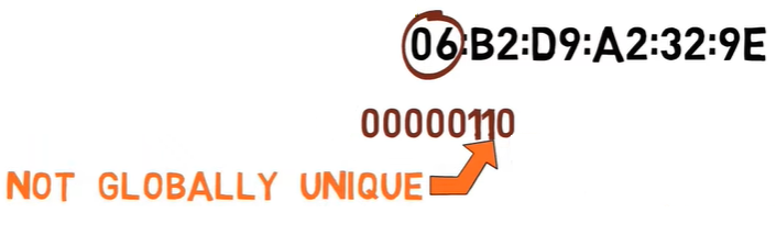
1, this address is not globally unique (Source: Brief)This bit is on, and thus we know that this address is actually not globally unique. IEEE will never assign this address to any vendor. So what is this address? Well, in this case it’s just one that I’ve made up. If I wanted to, I could assign it to a specific device. The fact that this bit is on declares that it is not globally unique.
Consider another address:
00:01:42:a9:c2:dd
The first byte is 00, so the second least significant bit is 0.

This is indeed a globally unique address, assigned to Cisco.
Ethernet Addresses – Recap
So, all in all, an Ethernet address has two main parts: The vendor ID, and the host ID.
There are also two special bits: the least significant bit within the most significant byte states whether the address is unicast or multicast. The second least significant bit within the most significant byte states whether the address is globally unique.
Why Does an Ethernet Frame Have a Minimum Length?
This is more of a "bonus" part of this post, and concerns collisions. Collisions is a very interesting topic, but since this post focuses on the Ethernet protocol, collisions will not be of our focus. I will therefore address this issue just briefly. While it's not crucial to understand in order to understand Ethernet frames, I promised a complete overview of the Ethernet protocol.
In the overview, I mentioned that an Ethernet frame consists of minimum 46 bytes of data and maximum 1500 of data. I already explained why we have that maximum limit, but what about the minimum?
To simplify our discussion, let's consider a network using classic Ethernet where all computers are attached to a single cable.

Let’s say A wants to send a message to B, and C wants to send a message to D. Let’s say that while A is transmitting its frame, C is also transmitting its frame. In this case, the frames will collide.

When this happens, we get errors – much like the case where two people start to speak in the same time, and it is impossible to understand either of them.
How are collisions handled in Ethernet?
Ethernet uses two main mechanisms to deal with collisions. The first is called CSMA, which stands for Carrier Sense Multiple Access. This basically means that when a station wants to transmit data, it first senses the channel to see if anyone else is transmitting by checking the signal level of the line. If the channel is in use, the station will wait and try again.
So, if A is transmitting, and C wants to send data, C will wait until A finishes its transmission before starting to transmit.
This is just like the case in a human conversation, where one person waits until the other stops talking, and only then does that person talk.
Yet, just like the case where two people might start talking at the same time, two Ethernet machines might start transmitting data at the same time. In this case, CD – Collision Detection – comes into play. Collision Detection means that the transmitting devices detect the fact that a collision has occurred. This is achieved by listening to the channel while transmitting.
For example, assume that station A transmits the bit stream 11001010. While transmitting, A is also listening to the channel. If no collision occurred, A would also read the signal 11001010 from the line.

If, however, a collision occurred, say with a frame sent by C, then A would read something different from the line – for instance, 11011010. This way, machine A realizes that its frame has collided.

Machine A can realize that a collision has occurred even before it finished transmitting the frame. Then, machine A stops transmitting and issues a JAM signal to tell the other station that a collision has occurred. As a result, both stations stop transmitting and wait a random interval of time before trying to submit again.
The amount of time that the stations wait increases with the number of collisions in the network. So on the first collision, A and C wait for a relatively short amount of time before transmitting again. If another collision occurs, they might wait longer.

Now, back to Ethernet. Ethernet requires that valid frames must be at least 64 bytes long, from destination address to checksum, including both. So, that data has to be at least 46 bytes long. If the frame is too short, then it must be padded.

One reason for having this minimum is directly related to the collision detection mechanism stated above.
Let's consider the following scenario. Host A wants to transmit a really really short frame to B, a frame that is only 1 byte long. I am exaggerating of course, this can’t really happen in Ethernet, but it will be helpful for the explanation.
Host A transmits this frame, which consists of 8 1s. Then, A listens to the channel while transmitting, and also reads 8 1s from it, reaching the conclusion that the frame has been transmitted successfully.
However, before the frame reaches the other end of the network, D starts transmitting a very short frame, one byte long, consisting of 8 0s. D listens to the channel while transmitting, and also reads 8 0s from it, concluding that the frame has been transmitted successfully.

Now, these two really short frames collide. Yet, neither A nor D are aware of this collision, as they have already concluded that the frame has been successfully delivered.
In order to avoid such cases, the frame must be long enough to prevent a station from completing its transmission before the first bit of the frame reaches the far end of the line. Having a minimum length for Ethernet frames solves this issue.
This was a very short discussion of collisions. If you’d like to know more about this topic, refer to the "additional resources" section below.
Conclusion
In this tutorial, we covered every bit and byte of the Ethernet protocol. You should now have a good understanding of this protocol, as well as a reference to consult when needed.
About the Author
Omer Rosenbaum is Swimm’s Chief Technology Officer. He's the author of the Brief YouTube Channel. He's also a cyber training expert and founder of Checkpoint Security Academy. He's the author of Computer Networks (in Hebrew). You can find him on Twitter.